Do wheel houses reduce the aerodynamic drag?
- Akshay Kumar Pakala

- Dec 2, 2020
- 6 min read
1) Introduction
In general, wheel houses are definitely equipped for almost all passenger vehicles. All passenger vehicles include either flat or curved wheel house (see Fig. 1.1). Significance of the wheelhouses is to protect the engine from any debris picked up by the rotating tire. These debris would travel and eventually destroy the car components, in absence of a wheelhouse for passenger vehicle. But, in the presence of wheelhouses, the tire and nearby engine components are protected from corrosion and nearby debris due to its fender lining.

(a) (b)
Figure 1.1: Wheel houses for passenger vehicles (a) Flat wheel house (b) Curved wheel house
We all know that a rotating tire accounts for additional drag of the vehicle, which in turn increases the amount of fuel consumption. Thus, a question arises, whether additional attachments to the tire such as wheel houses will increase or decrease the aerodynamic drag of the tire. To answer this question, a 2-D computational model is built and drag exerted on the tire and wheel houses are post processed and analyzed using Ansys Fluent.
Assumptions
steady state
In compressible adiabatic flow
viscous flow
Turbulent flow with w' = 0
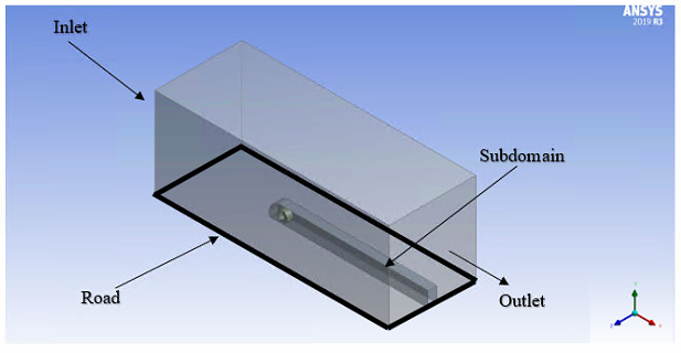
2) Geometry and mesh setup
Three computational domains are setup for the present study. To simulate the tire two dimensionally, a long cylinder with 10 deg deformation is assumed. The first computational domain, also identified as case 1, explores the aerodynamics of the rotating cylinder in the presence of a moving ground and absence of wheel house. The second and third computational simulations, identified as cases 2 and 3, involves a rotating cylinder in the presence of wheel houses (curved and flat).
By conducting a grid independent study, the dimensions of the enclosure and mesh sizes are calculated. Details and data analysis concerning the grid independent study is not disclosed in this blog but please refer to [1] for an in-depth information on this study.
After conducting the grid independence, dimensions of the enclosure are finalized. Figures concerning the dimensions of the finalized enclosure are given below.
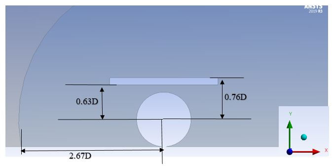
Figure 2.1: 2-D computational domain for the flat wheel house geometry (case 3)
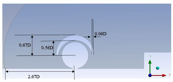
Figure 2.2: 2-D computational domain for the curved wheel house geometry (case 2)
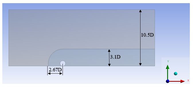
Figure 2.3: 2-D computational domain for the wheel without the wheel house (case 1)
3) Mesh
Mesh is generated within the enclosure, subdomain and around the tire and wheel to capture the velocity and pressure distributions of the air. After conducting a grid independence study, the required mesh size is calculated and applied around the 2-D long cylinder.
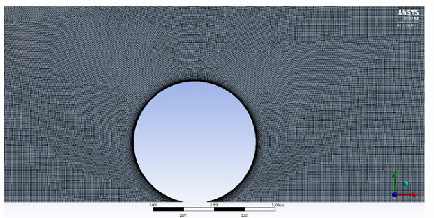
Figure 3.1: Mesh with inflation layer for case 1
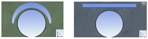
Figure 3.2: Mesh with inflation layer for cases 2 (left) and 3 (right)
Inflation layers are generated around the tire to capture the turbulent wall bounded effects. Using equations 3.1-3.5, that are given below, parameters of the inflation layers for instance, first layer thickness, no of inflation layers and growth rate, are decided.
Re_L= ρUL/μ 3.1
U_τ=√(τ_ω/ρ) 3.2
τ_ω=1/2 ρU^2*CF 3.3
CF =0.058Re_L^(-0.2) 3.4
y+ = (ρU_τ△y)/μ 3.5
Here, y+ is the non dimensional wall distance and △y is the first layer thickness. After approximating the first layer thickness, required no of inflation layers are decided to achieve a smooth transition of the mesh size from the edge of the inflation layer to the outer mesh.
4) Numerical setup
The present study is conducted for Reynolds number ranging from 10^5 to 10^6. By conducting verification and validation study, it is decided to utilize two turbulence models to approximate the aerodynamic drag and lift coefficients of the tire for this particular range of Reynolds number. The first turbulence model is k-transition turbulence model for Reynolds number ranging from 10^5 to 5x10^5 and the other is k-epsilon realizable turbulence model for Reynolds number ranging from 6x10^5 to 10^6. The verification and validation study also indicated to utilize a second order upwind scheme to decritize the momentum and turbulence model equations. Furthermore, a SIMPLEC algorithm to solve the k-transition turbulence model and a Coupled algorithm for k-epsilon realizable turbulence model is also realized from the results obtained from the verification and validation study. Refer [1] for more information on the verification and validation study.
5) Results
Table 5.1: Coefficient of drag for cases 1 and 2 at all Reynolds numbers
Reynolds number (10^5) Case 1 Case 2
1 1.95 0.94
2 1.88 1.38
3 1.91 0.87
4 1.82 1.18
5 1.86 0.83
6 1.07 0.98
7 1.06 0.98
8 1.08 1
9 1.04 0.98
10 1.04 0.95
After adding the curved wheel house to the tire (case 2), the drag coefficient significantly reduced at all Reynolds numbers (see Table 5.1). This indicates that the fuel efficiency of the vehicle can be increased after attaching a wheel house to the tire.
This decrease in drag coefficient due to the addition of the curved wheel house can be understood by analyzing the velocity and pressure distribution of the air around the tire for various Reynolds numbers. Separation point of the air from the tire is also post processed to understand the width of the wake region and its effects on drag coefficient.
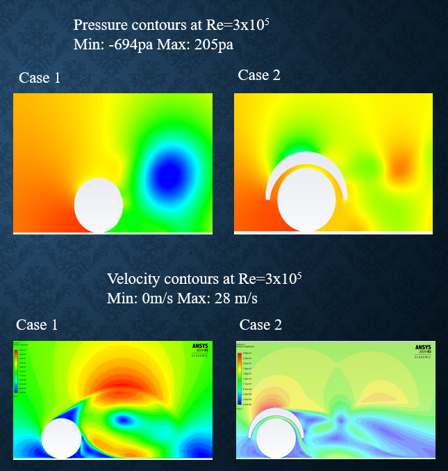
Figure 5.1: Pressure and velocity contours for cases 1 and 2 at Re=3x10^5
From the pressure contours it is clearly evident that a low pressure region is formed on the downstream side of the tire for case 1, compared to case 2. This will further increase the drag force on the tire for case 1, compared to case 2. This higher low pressure region for case 1 can be understood by analyzing the velocity contours. The velocity contours indicate a low velocity air on the downstream side of the tire for case 2, compared to case 1. According to Bernoulli's principle, the pressure of the air on the downstream side of the tire for case 2 is higher compared to case 1.
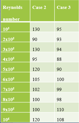
Table 5.2: Separation angle (in degrees and in clockwise direction) for cases 1 and 2 at all Reynolds number
Re(10^5) Case 1 Case 2
10 48 130
2 60 90
3 63 130
4 67 95
5 65 120
6 78 105
7 80 102
8 82 100
9 85 100
10 87 120
The separation points, when post-processed, also state a decrease in the width of the wake region for case 2, compared to case 1.
Now that it is confirmed that adding a wheel house decrease the drag of the tire, the next step is to analyze the effects of wheel house geometry on the tire. Non aerodynamic wheel houses can generate serious amount of drag force on the tire. To grasp this issue, the drag coefficient values acting on the tire for a flat wheel house are post processed for the Reynolds number ranging from 10^5 to 10^6 and these values are then compared to the drag coefficient values of the tire for case 2 with curved wheel house.
Table 5.3: Drag coefficient values for cases 2 and 3 at all Reynolds numbers
Re(10^5) Case 2 Case 3
1 0.94 1.31
2 1.38 1.28
3 0.87 1.3
4 1.18 1.24
5 0.83 1.2
6 0.98 1.57
7 0.98 1.21
8 1 1.22
9 0.98 1.4
10 0.95 1.74
The post processed drag coefficients state that the drag is increased for case 3, compared to case 2, for all Reynolds numbers (see Table 5.3). To understand this increase in the drag coefficient for case 3, pressure, velocity contours for the flat wheel houses are plotted and compared to case 2.

Figure 5.2: velocity contours for cases 2 and 3
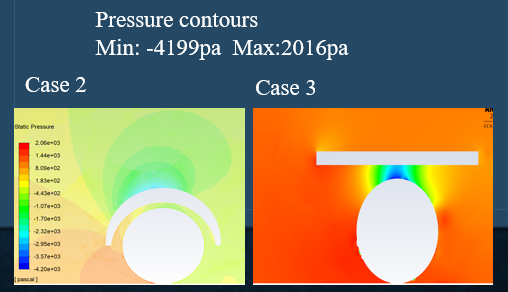
Figure 5.3: pressure contours for cases 2 and 3
Due to the non aerodynamic shape of the flat wheel house, the fluid separates at the upstream edge of the wheel house for case 3 (see Table 5.4). This results in an increase in the width wake region and causes an increase in the drag force for case 3, compared to case 2. The velocity of the fluid on the downstream side of the tire is increased for case 3, compared to case 2 (see Fig. 5.3). According to Bernoulli's principle, this decreases the pressure the air on the downstream side of the tire for case 3, compared to case 2. Which in turn increases the drag force that is exerted on the tire for case 3, compared to case 2.
Table 5.4: Separation angles for cases 2 and 3 at all Reynolds numbers
In conclusion, wheel houses decreases the drag coefficient of the tire but geometry of wheel house is also important.
References
[1] Pakala, A. K., 2020, "Aerodynamic Analysis of Conventional and Spherical Tires," MS. c thesis, University of Akron.
Important note: Information, pictures, graphs, tables and data presented in this blog is borrowed from Akshay Kumar Pakala's Master's thesis document.
Comments